|
|
CIVE 530 - OPEN-CHANNEL HYDRAULICS
LECTURE 10: THE HYDRAULIC JUMP (CHOW CHAPTER 15)
|
- The theory of the jump developed from nearly horizontal channels, where the effect of gravity is negligible.
- The results appear to apply to most channels encountered in engineering problems.
- For channels of large slope, this effect may not be negligible.
- Practical applications of the jump are:
- To dissipate energy in water flowing over dams, weirs, and other hydraulic structures, and to prevent scouring downstream from the structures.
- To recover head or raise the water level on the downstream side of a measuring flume.
- To increase weight on an apron and thus reduce uplift pressure under a masonry structure.
- To increase the discharge of a sluice by holding back tailwater, since the effective head will be reduced if the tailwater is allowed to drown the jump.
- To indicate special flow conditions, such as the existence of supercritical flow.
- To mix chemical used for water purification.
- To aerate water for city water supplies.
- To remove air pockets from water-supply lines and thus, prevent air locking.
|
15.2 JUMP IN HORIZONTAL RECTANGULAR CHANNELS
|
- A hydraulic jump will form in a channel if the upstream
flow depth y1, the downstream flow depth y2, and the Froude number of the upstream flow F1
satisfy the equation:
|
y2/y1 = (1/2) [(1 + 8F12)1/2 -1]
|
- This equation is shown in the following figure:
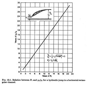
Fig. 15-1 (Chow)
|
|
- Hydraulic jumps can be classified according to the upstream flow Froude number, as follows:
- F1 = 1-1.7. Undular jump.
- F1 = 1.7-2.5. Weak jump.
- F1 = 2.5-4.5. Oscillating jump.
- F1 = 4.5-9.0. Steady jump.
- F1 > 9.0. Strong jump.
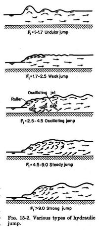
Fig. 15-2 (Chow)
|
|
|
15.4 BASIC CHARACTERISTICS OF THE JUMP
|
- The length of the jump may be defined as the distance measured from the front face of the jump to a point on the surface immediately downstream
from the roller.
- This length cannot be determined easily by theory, but it has been experimentally investigated by many hydraulicians.
- The experimental data can be plotted as L/y2 vs. F1, as shown in Fig. 15-4.
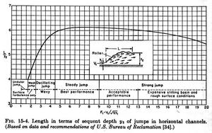
Fig. 15-4 (Chow)
|
|
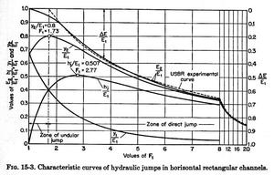
- The surface profile of a jump can be represented by dimensionless curves, as shown in Fig. 15-5.
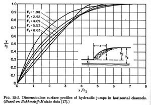
Fig. 15-5 (Chow)
|
|
- Other measurements have shown that the actual length of the jump may be as much as 20% longer than that shown in Fig. 15-5.
|