FALL 2009
FINAL EXAM
MONDAY, DECEMBER 14, 2009, 0800-1000
Name: ______________________ Red ID __________________ Grade: _________
- (25%) A planned reservoir has a total capacity of 5 million cubic meters (5 hm3).
The catchment drainage area is 200 km2.
The mean annual runoff in the basin is 500 mm.
The sediment yield is 1,350 Metric tons/km2/yr.
The specific weight of sediment deposits is estimated at 13,000 N/m3.
The sediments are coarse grained.
How long will it take the reservoir to fill up to 80% capacity?
Use five increments of reservoir capacity.
The mean annual water inflow is:I = 500 mm × 200 km2
I = 500 mm × 200 km2 × 100 hm2/km2 × 0.001 m/mm × 0.01 hm/m
I = 100 hm3
The annual sediment inflow is:
Is =
1350 M.tons/km2/yr × 1000 kg/M.tons × 200 km2 × 9.81 N/kg / (13000 N/m3 × 1000000 m3/hm3)
Is = 0.204 hm3/yr
Interval Reservoir capacity (hm3) Accumulated volume (hm3) C/I ratio Average C/I in interval Trap efficiency (%) Number of years to fill Cumulative number of years to fill 0 5 0 0.05 - - - - 1 4 1 0.04 0.045 83 5.9 5.9 2 3 2 0.03 0.035 80 6.1 12.0 3 2 3 0.02 0.025 75 6.5 18.5 4 1 4 0.01 0.015 64 7.7 26.2
- (20%) Calculate the diameter of a concrete culvert to pass the 50-yr flood, with Q50 = 265 cfs.
The inlet invert elevation is z1 = 180 ft.
The natural streambed slope is So = 0.01. The tailwater depth above the outlet invert is y2 = 4.2 ft.
The culvert length is 250 ft.
The roadway shoulder elevation is 196 ft.
Assume a 2-ft freeboard. Assume a circular concrete culvert (f = 0.018, n = 0.012), and square edge with headwalls.
THE DESIGN ELEVATION FOR U/S POOL IS: 196 - 2 = 194 FT.
FIRST ASSUME OUTLET CONTROL.
ASSUME THAT THE HGL IS AT THE ELEVATION OF THE D/S POOL.
CALCULATE OUTLET INVERT ELEVATION: z2 = 180 - (0.01 × 250) = 180 - 2.5 = 177.5 FT.
CALCULATE D/S POOL ELEVATION: 177.5 + 4.2 = 181.7 FT.
SET UP ENERGY EQUATION: z1 + y1 + V12/(2g) = z2 + y2 + V22/(2g) + ∑hL
ASSUME V1 = 0 [VELOCITY IS ZERO IN THE U/S POOL]
ASSUME V2 = 0 [VELOCITY DISSIPATES TO ZERO IN THE D/S POOL]
∑hL = [Ke + KE + f(L/D)] V2/(2g)
ASSUME Ke = 0.5; KE = 1. [TABLE 5-3]
ASSUME f = 0.018
ENERGY EQUATION: 194 = 181.7 + [0.5 + 1.0 + 0.018 (250/D)] V2/(2g)
12.3 = [1.5 + 4.5/D] V2/(2g)
V = Q/A = 265/A = 265/[(π/4)D2]
V2/(2g) = { 2652/[(π/4)2D4] } / (2g)
12.3 = 2652 [1.5 + 4.5/D] / [(π/4)2D4 (2 × 32.17)]
SOLVE BY TRIAL AND ERROR: D = 4.3 FT.
CHOOSE NEXT LARGER SIZE: D = 4.5 FT.
WITH Q = 265, AND D = 4.5 FT = 54 IN, ENTER FIG. 7-5 TO FIND RATIO HEADWATER DEPTH OVER DEPTH HW/D = 3.0
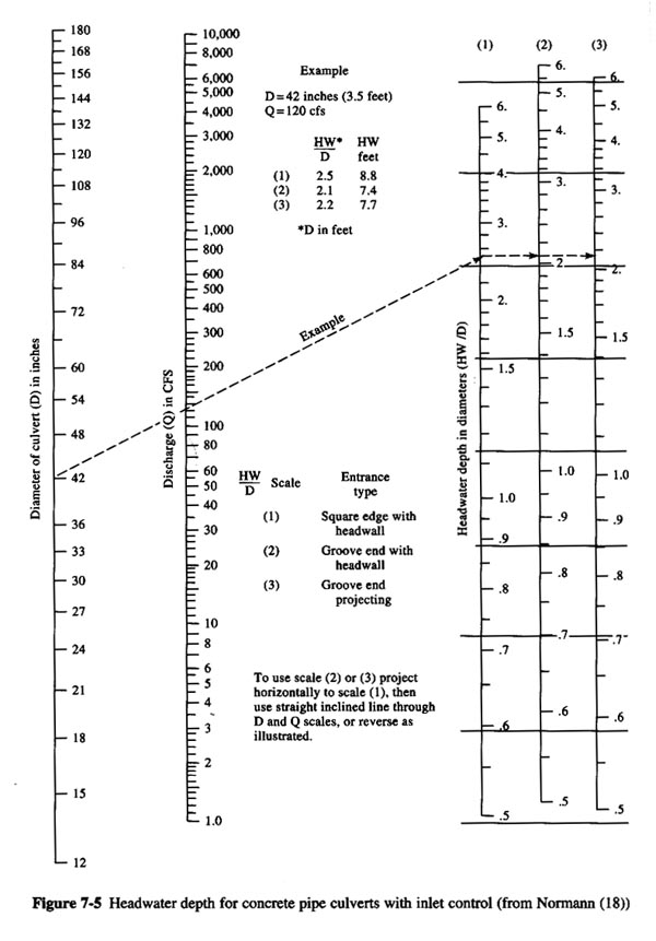
HW DEPTH = 3.0 × 4.5 = 13.5 FT.U/S POOL ELEVATION = 180 + 13.5 = 193.5 SMALLER THAN 194. OK.
CHECK CRITICAL DEPTH.
COMPUTE THE SECTION FACTOR: Q/(g1/2do5/2) = 265 / [32.17)1/2(4.5)5/2] = 1.09
ENTER FIG. 4-15, WITH SECTION FACTOR 1.09: yc/do = 0.95
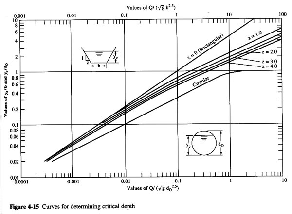
THUS: yc = 4.28 FT. ANSWER.CHECK NORMAL DEPTH.
ASSUME n = 0.013.
COMPUTE THE SECTION FACTOR: Qn/(1.486 × So1/2 × do8/3 ) = 265 × 0.012 / (1.486 × 0.011/2 × 4.58/3) = 0.38
ENTER FIG. 4-7, WITH SECTION FACTOR 0.38: yn/do = 0.8
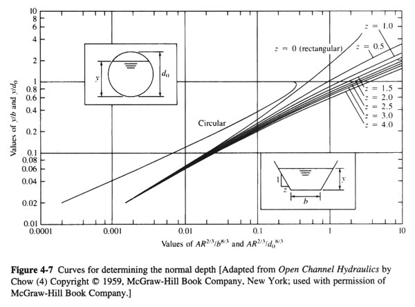
THUS: yn = 3.6 FT. ANSWER.BECAUSE yn < yc, THE FLOW IS SUPERCRITICAL.
BECAUSE TW < yc, THERE WILL BE NO HYDRAULIC JUMP NEAR THE OUTLET.
BECAUSE THE FLOW IS SUPERCRITICAL IN THE PIPE AND THE OUTLET IS OPEN TO THE ATMOSPHERE (TW DEPTH < D) WE CAN CONCLUDE THAT THERE IS INLET CONTROL.
DESIGN DIAMETER: D = 4.5 FT = 54 IN. ANSWER.
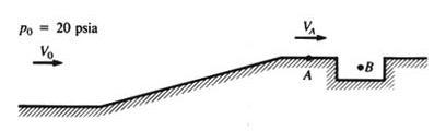
- (20%) Given Vo = 8 fps and VA = 12 fps at po = 20 psia,
calculate the pressure coefficient Cp and the velocity
Vo that will just begin to cause cavitation in the slot. Assume T = 70oF.
VA = Vo(1 - Cp)1/2
Cp = 1 - (VA2/Vo2)
Cp = 1 - (122/82) = -1.25 ANSWER.
σi B = 1 - 2 Cp = 1 - 2 (-1.25) = 3.5
σi B = (po - pv) / (ρVo2 /2)
T= 70oF: pv = 0.363 psia
3.5 = (20 × 144 in2/ft2 - 0.363 × 144 in2/ft2) / (ρ Vo2 /2)
3.5 = (2880 - 52.27) / (1.94 Vo2 /2)
Vo = 28.86 fps. ANSWER.
- (20%) Given the system shown below, what is the discharge Q (m3/s) and corresponding head H (m) at the system operating point? Assume sharp entrance and exit losses. Assume f = 0.018.
The performance curve of the pump is given by: H = 60 - 600 Q2

hp = (z2 - z1) + [V2/(2g)] [f (L/D) + ∑ KL ]
hp = (z2 - z1) + [ Q2/(2gA2)] [ f (L/D) + Ke + Kb + KE ]
From Table 5-3 (in the text): Ke = 0.5; Kb = 0.19; KE = 1
hp = (500 - 450) + [ Q2/(2g ((π/4) D2)2) ] [ 0.018 (2000/0.5) + 0.5 + 0.19 + 1 ]
hp = 50 + [ Q2/(2 (9.81) ((π/4)2 (0.5)4)) ] (73.69)
hp = 50 + [ Q2/(0.7564) ] (73.69)
hp = 50 + 97.42 Q2
Pump performance curve: H = 60 - 600 Q 2
At H = hp: Q = 0.1197 m3/s ANSWER.
hp = 50 + 97.42 (0.1197) 2 = 51.395 m. ANSWER.
- (20%) What head ΔH (m) will be developed for an axial-flow pump of D = 0.3 m operating at n = 900 rpm and discharging Q = 100 L/s? What power P (KW) will be required?
The pump dimensionless performance curves are shown below.
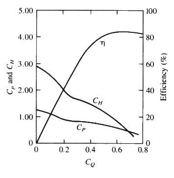
Q = 100 L/s = 0.1 m3/s
n = 900 rpm = 900 rpm / 60 s/m = 15 rps
CQ = Q/(nD3) = 0.1 /(15 × 0.33) = 0.247
CH = 1.78
CP = 0.81
CH= ΔH / (D2 n2 / g)
ΔH = CH D2 n2 / g = 1.78 × 0.32 × 152 / 9.81
ΔH = 3.67 m ANSWER.
CP = P / (ρ D5 n3)
P = CP ρ D5 n3
P = 0.81 × 1 × 0.35 × 153
P = 6.64 KN m/s
P = 6.64 KW ANSWER.