SPRING 2016
FINAL EXAM
FRIDAY, MAY 6, 2016, 1400-1600
Name: ______________________ Red ID __________________ Grade: _________
(25%) A 5-m high diversion dam is planned on a channel operating at critical flow. The channel is rectangular, with Q = 100 m3/s, bottom width b = 4.7 m, bottom slope So = 0.01, and Manning's n = 0.023. Calculate the length of the C1 water-surface profile. Compare with the results of onlinecalc.sdsu.edu/onlinewsprofiles31.php. Explain the difference, if any.
The unit-width discharge is: q = 100/4.7 = 21.276 m2/s.
The critical depth: yc = (q2/g)1/3 = 3.587 m.
The length L of the C1 water surface profile: L = (5 - 3.587) / 0.01 = 141.3 m.
The result of onlinewsprofiles31.php is: L= 139.71 m.
The minor difference is due to the fact that the first calculation is independent of a frictional value (critical flow), while the second (the calculator value) is based on the stated Manning's n.
(25%) A planned reservoir has a total capacity of 10 million cubic meters. The catchment drainage area is 200 km2. The mean annual runoff in the basin is 500 mm. The sediment yield is 1,350 Metric tons/km2/yr. The specific weight of sediment deposits is estimated at 13,000 N/m3. The sediments are coarse grained. How long will it take the reservoir to fill up to 80% capacity? Use ten (10) increments of reservoir capacity.
The mean annual water inflow is:
I = 500 mm × 200 km2
I = 500 mm × 0.001 m/mm × 200 km2 × (1000 m/km)2 = 100,000,000 m3
The annual sediment inflow is:
Is = 1350 M.ton/km2/yr × 1000 kg/M.ton × 200 km2 × 9.81 N/kg / (13000 N/m3)
Is = 203,746 m3/yr
Interval Reservoir
capacity
(million m3)Accumulated
volume
(million m3)C/I ratio Average C/I in interval Trap efficiency (%) Number of years to fill Cumulative number of years to fill 0 10 0 0.1 - - - - 1 9 1 0.09 0.095 93 5 5 2 8 2 0.08 0.085 92 6 11 3 7 3 0.07 0.075 90 5 16 4 6 4 0.06 0.065 89 6 22 5 5 5 0.05 0.055 87 5 27 6 4 6 0.04 0.045 84 6 33 7 3 7 0.03 0.035 80 6 39 8 2 8 0.02 0.025 75 7 46 9 1 9 0.01 0.015 64 7 53 10 0 10 0 0.005 39 13 66
(20%) Calculate the diameter of a concrete culvert to pass the 50-yr flood, with Q50 = 320 cfs. The inlet invert elevation is z1 = 180 ft. The natural streambed slope is So = 0.01. The tailwater depth above the outlet invert is y2 = 4.2 ft. The culvert length is L = 250 ft. The roadway shoulder elevation is 196 ft. Assume a 2-ft freeboard. Assume a circular concrete culvert (n = 0.013), and square edge with headwalls.
The culvert has the following conditions:
Design discharge: Q = 320 cfs.
Return period: T = 50 yr.
Culvert length: L = 250 ft.
Bottom slope: So = 0.01.
Culvert material: Concrete.
Manning's n = 0.013.
Inlet invert elevation: z1 = 180 ft.
Roadway shoulder elevation: Es = 196 ft.
Tailwater depth above outlet invert: TW = y2 = 4.2 ft.
Freeboard: Fb = 2 ft.
SolutionThe design elevation for the upstream pool is: Es - Fb = 196 - 2 = 194 ft.
A circular concrete pipe, with square edge with headwalls.
Assume outlet control.
Calculate the outlet invert elevation: z2 = z1 - (So L) = 180 - (0.01 × 250) = 177.5 ft.
Calculate the downstream pool elevation: z2 + y2 = 177.5 + 4.2 = 181.7 ft.
Set up the energy balance:
V12 V22
z1 + y1 + _____ = z2 + y2 + _____ + ∑hL
2g 2g(8-1) Assume V1 = 0, i.e., the velocity is zero in the upstream pool.
Assume V2 = 0, i.e., the velocity dissipates to zero in the downstream pool.
The head loss ∑hL is equal to the sum of entrance losses (with loss coefficient Ke), exit losses (with loss coefficient KE), and barrel losses.
Using the Darcy-Weisbach equation, the head loss is:
V 2
∑hL = [ (Ke + KE + f (L / D ) ] _____
2g(8-2) Ke = 0.5 and KE = 1
The relation between Darcy-Weisbach friction factor f and Manning's n is :
8 g n 2
f = __________
k 2R 1/3(8-3) in which k = 1 in SI units, and k = 1.486 in U.S. Customary units.
In U.S. Customary units, with k = 1.486, and g = 32.17 ft/s2:
116.55 n 2
f = ____________
R 1/3(8-4) For a circular pipe: R = D / 4. Therefore:
185.01 n 2
f = ____________
D 1/3(8-5) From Eq. 8-1, the energy balance reduces to:
z1 + y1 = z2 + y2 + ∑hL
(8-6)
194 = 181.7 + ∑hL
(8-7) The head loss equation (Eq. 8-2) is repeated here for convenience:
V 2
∑hL = [ (Ke + KE + f (L / D ) ] _____
2g
(8-2)
Replacing Eq. 8-5 in Eq. 8-2:
V 2
∑hL = [ 0.5 + 1.0 + (185.01 n 2 L / D 4/3 ) ] _____
2g
(8-8) Combining Eqs. 8-7 and 8-8:
V 2
12.3 = [ 1.5 + (7.817 / D 4/3 ) ] _____
2g(8-9) The flow velocity is: V = Q / A.
Therefore: V = 320 / A = 320 / [ (π/4) D 2 ]
The velocity head is: V 2 / (2g) = { 3202 / [ (π/4)2 D 4 ] } / (2g) = 2580 / D 4
Replacing the velocity head in Eq. 8-9:
2580
12.3 = [ 1.5 + (7.817 / D 4/3 ) ] _______
D 4(8-10) Solving Eq. 8-10 by iteration: D = 4.8 ft. For design purposes, assume the next larger size: D = 5.0 ft.
With Q = 320 cfs, D = 5 ft = 60 in, enter Fig. 8-9 to find the ratio of headwater depth to diameter HW/D = 2.8, for the case of square edge with headwalls (1).
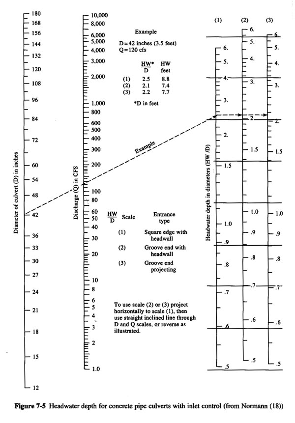
The headwater depth is: HW = (HW/D) × D = 2.8 × 5.0 = 14 ft.
The upstream pool elevation is: 180 + 14 = 194 ft. This upstream pool elevation is equal to 194 ft; therefore, the design is OK.
Calculate the normal depth using ONLINE CHANNEL 06: yn = 4.81 ft.
Calculate the critical depth using ONLINE CHANNEL 07: yc = 4.735 ft.
Since yn > yc, the flow is subcritical.
Since TW = 4.2 < yn = 4.810, there will be a hydraulic drop at the outlet.
Since the flow is subcritical, inlet control is not certain.
The design diameter is: D = 5.0 ft = 60 in. ANSWER.
(20%) What head ΔH (m) will be developed for an axial-flow pump of D = 0.3 m operating at
n = 900 rpm and discharging Q = 100 L/s? What power P (KW) will be required? The pump dimensionless performance curves are shown below.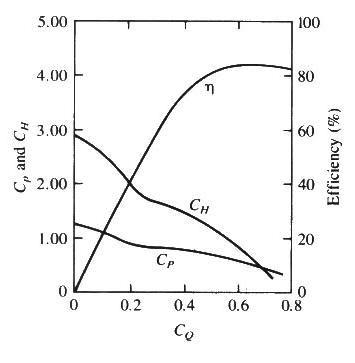
Q = 100 L/s = 0.1 m3/s
n = 900 rpm = 900 rpm / 60 s/m = 15 rps
CQ = Q/(nD3) = 0.1 /(15 × 0.33) = 0.247
CH = 1.78
CP = 0.81
CH = ΔH / (D2 n2 / g)
ΔH = CH D2 n2 / g = 1.78 × 0.32 × 152 / 9.81
ΔH = 3.67 m ANSWER.
CP = P / (ρ D5 n3)
P = CP ρ D5 n3
P = 0.81 (1.0 KNs2/m4) (0.35 m5) (153 s-3)
P = 0.81 × 1 × 0.35 × 153
P = 6.64 KN m/s
P = 6.64 KW ANSWER.
(20%) Given the system shown below, what is the discharge Q (m3/s) and corresponding head H (m) at the system operating point? Assume very smooth entrance and sharp exit losses. Assume Manning's n = 0.013. The performance curve of the pump is given by: H = 80 - 630 Q2

hp = (z2 - z1) + [V2/(2g)] [f (L/D) + ∑ KL ]
hp = (z2 - z1) + [ Q2/(2gA2)] [ f (L/D) + Ke + Kb + KE ]
From Table 5-3 (in the text): Ke = 0.03; Kb = 0.19; KE = 1
hp = (500 - 450) + [ Q2/(2g ((π/4) D2)2) ] [ f (2000/0.5) + 0.03 + 0.19 + 1 ]
f = 8 g n2 / R1/3
f = 8 (9.81) (0.013)2 / (D/4)1/3
f = 8 (9.81) (0.013)2 / (0.5/4)1/3
f = 8 (9.81) (0.013)2 / (0.125)1/3
f = 0.0265
hp = (500 - 450) + [ Q2/(2g ((π/4) D2)2) ] [ 0.0265 (2000/0.5) + 0.03 + 0.19 + 1 ]
hp = 50 + [ Q2/(2 (9.81) (π/4)2 (0.5)4) ] (107.22)
hp = 50 + [ Q2/(0.7564) ] (107.22)
hp = 50 + 141.75 Q2
Pump performance curve: H = 80 - 630 Q 2
At H = hp:
80 - 630 Q 2 = 50 + 141.75 Q2
30 = 771.75 Q2
Q = 0.197 m3/s ANSWER.
H = hp = 50 + 141.75 (0.197) 2 = 55.5 m. ANSWER.