CIV E 444 - APPLIED HYDRAULICS
FALL 2009
HOMEWORK No. 10 SOLUTION
- The upstream design pool elevation [HW elevation] is = 112 - 2 = 110 ft.
The downstream invert elevation is z2 = 100 - (So L) = 100 - (0.02 × 200) = 96 ft.
The downstream pool elevation [TW elevation] is = 96 + 4 = 100 ft.
First assume outlet control, and apply the energy equation between u/s and d/s. Velocities are zero in the u/s and d/s pools.
110 = 100 + [Ke + KE + f (L/D)] [V2/(2g)]
10 = [0.5 + 1.0 + 0.015 (200/D)] [V2/(2g)]
[V2/(2g)] = Q2/ { [(π/4)D2]2 2g } = (220)2/(0.6168 × 64.4 × D 4) = 1218 / D4
10 = [1.5 + (3/D)] (1218 / D4)
Solve by trial and error: D = 4.1 ft. Assume D = 4.5 ft = 54 in.
From Fig. 7-5, HW/D = 2.4
HW depth = 2.4 × 4.5 = 10.8 ft.
HW elevation = 100 + 10.8 = 110.8 ft. [Too high!]
Next assume D = 5 ft.
From Fig. 7-5, HW/D = 1.7
HW depth = 1.7 × 5 = 8.5 ft.
HW elevation = 100 + 8.5 = 108.5 ft. [OK]
Check critical depth: Q / (g1/2do5/2) = 220 / [(32.2)1/2 (5)5/2] = 0.69
From Fig. 4-15: yc / do = 0.85
yc = 4.25 ft.
Calculate normal depth: (Q n) / (1.49 S1/2 do8/3) = (220 × 0.013) / (1.49 × 0.14142 × 73.1) = 0.19
yn / do = 0.55
yn = 2.75 ft.
The flow is supercritical.
Since TW = 4 < yc = 4.25, there will be no hydraulic jump in the culvert.
Since the outlet is open to the atmosphere, there is inlet control.
- HD = 1.0 m.
P = 170 - 155 = 15 m.
P / HD = 15
From Fig. 7-10 (a) below: CD = 0.492
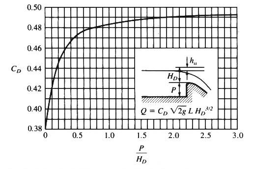
Q = C (2g)1/2 L H3/2 = 53.15 C H3/2
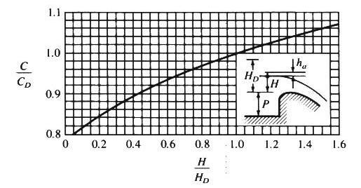
Spillway rating is shown in the following table. Head H (Col. 2) is elevation above the crest.
The ratio C/CD (Col. 4) is obtained from Fig. 7-10 (b) (below) for each H / HD.
Elevation (m) (1)
H (m) (2)
H / HD (3)
C / CD (4)
C (5)
H3/2 (6)
Q (m3/s) (7)
170.0 0.0 0.0 0.00 0.000 0.00 0.000 170.2 0.2 0.2 0.842 0.414 0.0894 1.967 170.4 0.4 0.4 0.895 0.440 0.253 5.917 170.6 0.6 0.6 0.935 0.460 0.465 11.369 170.8 0.8 0.8 0.968 0.476 0.715 18.089 171.0 1.0 1.0 1.000 0.492 1.000 26.150 171.2 1.2 1.2 1.025 0.504 1.314 30.377 171.4 1.4 1.4 1.048 0.516 1.656 45.416 171.6 1.6 1.6 1.070 0.526 2.024 56.585
- Q = (2/3) (2g)1/2 C L (H13/2 - H23/2)
H1 = 5 ft; d = 1 ft.
H2 = H1 - d = 4 ft.
d / H1 = 1/ 5 = 0.2
From Fig. 7-11: C = 0.7
Qd = 1 = (2/3) (2 × 32.2)1/2 (0.7) (100) [(5)3/2 - (4)3/2] = 1,191 cfs.
If gate opening is raised 0.5 ft: d = 1.5 ft.
H2 = H1 - d = 3.5 ft.
d / H1 = 1.5/ 5 = 0.3
From Fig. 7-11: C = 0.684
Qd = 1.5 = (2/3) (2 × 32.2)1/2 (0.684) (100) [(5)3/2 - (3.5)3/2] = 1,695 cfs.
- Do/D1 = 24 / 8 = 3
The pressure coefficient is defined as: V1 = Vo (1 - Cp)1/2
Cp = 1 - (V1/Vo)2 = 1 - (Do/D1)4 = - 80
The free-vortex incipient cavitation index is: σi, A = 1 - 2 Cp = 1 - [2 × (- 80)] = 161
pv = 37 psf
σi = (po - pv) / (ρVo2 /2)
161 = [(25 × 144 in2/ft2) - 37)] / [ 1.94 Vo2/2]
Vo = 4.78 fps
Q = Vo Ao = Vo (π/4) Do2 = 4.78 (0.7854) (2)2 = 15 cfs.